
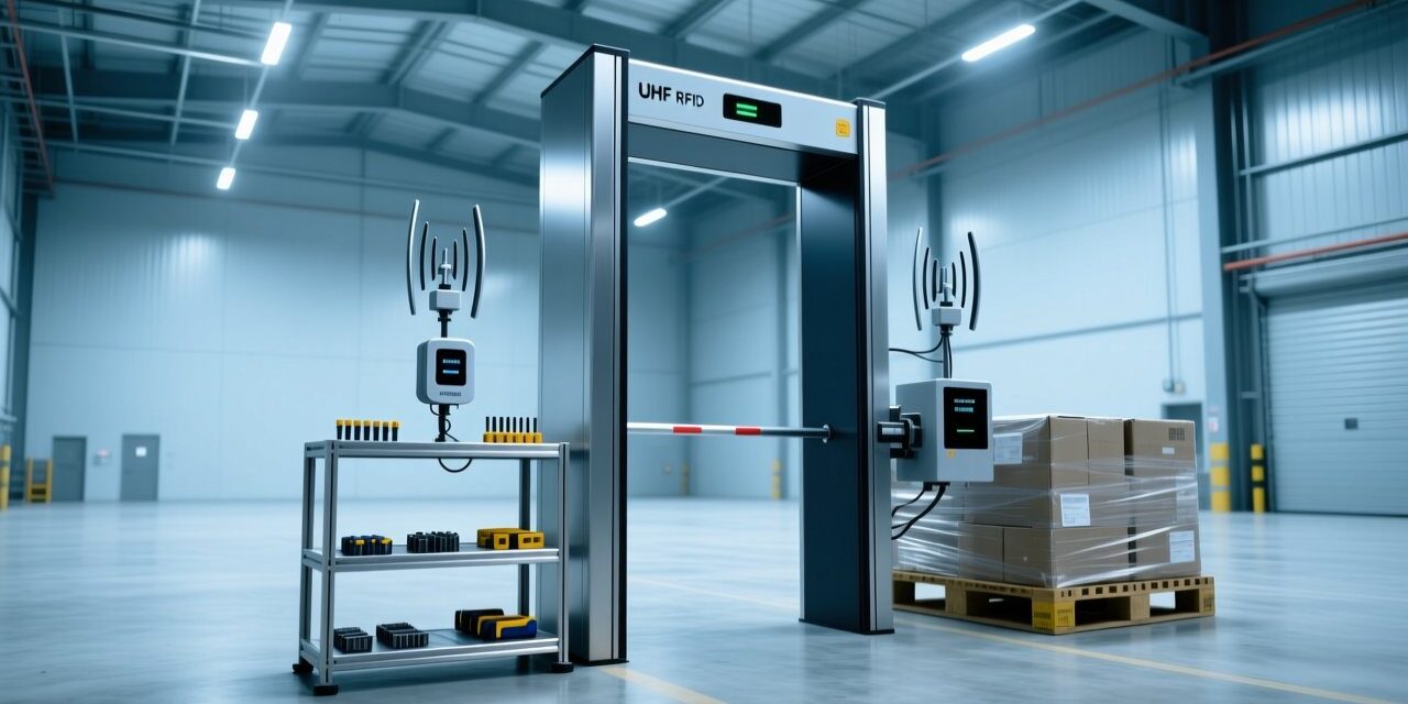
Understanding the Role of RFID Reader Antennas in Modern Asset Tracking
RFID technology has become a cornerstone of supply chain digitization, with the global passive RFID market projected to exceed $20 billion by 2027. Yet, even the most advanced lecteur RFID fixe can underperform if paired with the wrong antenna. Antenna selection directly impacts read accuracy, energy efficiency, and the size of the read zone—parameters that system integrators and field engineers must master to deliver reliable solutions. This article distills the technical fundamentals and practical deployment considerations for UHF RFID antennas, comparing near-field and far-field designs across common industrial scenarios.
Market Drivers and Deployment Challenges
Industries from retail inventory management to warehouse logistics are adopting RFID at an accelerating pace. Applications now range from item-level tagging in apparel stores to pallet tracking at shipping docks. Each environment demands a specific antenna radiation pattern to avoid misreads or dead zones. Near-field antennas excel at close‑range, dense‑tag environments where magnetic coupling prevents stray reads of adjacent items. Far-field antennas, leveraging electromagnetic wave propagation, provide the long read ranges needed for portal and dock‑door setups. Understanding these core differences helps engineers avoid deployment pitfalls such as phantom reads or insufficient coverage.
Technical Comparison: Near-Field vs Far-Field Antennas
| Paramètre | Near-Field UHF Antenna | Far-Field UHF Antenna |
|---|---|---|
| Coupling Mechanism | Magnetic (inductive) coupling | Electromagnetic wave (radiative) coupling |
| Typical Read Range | 0–30 cm | 1–12 m (depending on gain and regulations) |
| Read Zone Shape | Confined, spherical near the antenna surface | Elliptical or conical, extended in front of the antenna |
| Gain (dBi) | Typically 0–4 dBi | 6–12 dBi |
| Polarization | Often dual‑polarized or circular for tag orientation independence | Linear or circular; circular preferred for dynamic tag orientation |
| Ideal Use Cases | Item‑level identification, pharmaceutical vials, small tools, kiosks | Portal gates, Transporteuses, dock doors, vehicle identification |
Near-field antennas generate a strong magnetic field that decays rapidly with distance, creating a well‑defined read volume. This characteristic is essential when tagging closely packed Étiquettes RFID on shelves or in bins, as it avoids cross‑reads. Far-field antennas, in contrast, radiate energy over longer distances and require careful tuning of radiated power and receive sensitivity to maintain read zone boundaries.
Read Zone Design: Tailoring Coverage to the Application
The term “uhf antenna read zone design” encompasses the spatial volume where a tag can be reliably read. For a portal reader, engineers often use two or four far-field antennas arranged to create an overlapping zone that captures tags regardless of their orientation on a forklift or pallet. A typical warehouse portal may employ 9–12 dBi RFID antennas with circular polarization to maintain performance as goods pass through. Cependant, without precisely adjusted power levels, the far‑field pattern can overshoot, causing reads of tags in neighboring lanes. This is where blocker antennas or RF‑shielding panels are introduced.
RFID Blocker Antenna vs Portal
Un rfid blocker antenna is a dedicated far-field antenna that radiates a masking signal or creates an RF dead zone to “blind” unwanted tags. It is often used in retail checkout stations to prevent the bagging area from reading items still in the cart. En revanche, a portal antenna focuses on capturing all tags within a defined passage. Combining blocker antennas with portal antennas lets integrators sculpt the read zone, achieving high accuracy without interference from adjacent areas—a critical requirement in high‑density warehouse settings.
Antenna Gain vs Read Range: The Trade-Off
Antenna gain directly influences the antenna gain vs read range equation. Higher gain concentrates energy in a narrower beam, extending range but shrinking coverage width. Par exemple, un 12 dBi antenna may read passive UHF tags at up to 12 mètres, but its –3 dB beamwidth might be only 30–40°, creating a “spotlight” effect. This is ideal for long‑range conveyor reading where tags pass through a fixed point. À l’inverse, a lower‑gain antenna (par exemple, 6 dBi) with a wider beam can cover a broader area at shorter range, suitable for shelf‑mounted smart retail displays. Engineers must balance gain with the physical constraints of the site: metal racks, tag backscatter, and multi‑path reflections can degrade performance if the beam is too narrow or too wide.
Near-Field UHF Antenna Details and Use Cases
A near field uhf antenna is designed for close‑proximity reading of on-metal RFID tags or tiny items where far-field radiation would miss or cause interference. These antennas often incorporate a ferrite core or loop structure to generate a concentrated H‑field. In pharmaceutical track‑and‑trace, a near-field antenna mounted under a conveyor belt reads each vial as it passes within millimeters, achieving 99.9% read rates without cross‑reads from adjacent lanes. Another example is tool cabinet management: placing UHF near‑field antennas in each drawer ensures precise identification of every tool, even when tools are stacked.
Practical Deployment and Selection Tips
- Map the environment first: Use a spectrum analyzer or a handheld handheld RFID scanner to identify sources of interference and dead zones.
- Match antenna to tag: On‑metal applications demand specialized antennas and tamper‑proof flexible UHF RFID on‑metal tags; verify the antenna’s impedance matching and tag sensitivity.
- Consider polarization: For tags in random orientation, choose circularly polarized antennas. Linear polarization offers slightly longer range but requires consistent tag alignment.
- Plan for field strength limits: Regulatory bodies (FCC/ETSI) set maximum radiated power; near-field antennas generally operate at lower power but must still comply.
- Use simulation tools: Software such as FEKO or CST can model read zones and help optimize antenna placement before physical installation.
FAQ
Can I use a single antenna type for both near-field and far-field applications?
Some dual‑purpose antennas exist, but performance is usually compromised in one mode. Dedicated near-field antennas provide far better isolation and read consistency for close‑range tasks.
How do I decide between 4‑port and 8‑port readers for a portal?
The number of ports depends on the number of independent antenna beams required. Most standard dock‑door portals use four antennas (one per side). An 8‑port reader offers redundancy or the ability to combine near‑field and far‑field arrays.
Does a higher gain always mean a better antenna?
Not necessarily. High gain narrows the beam, which can create coverage holes. For uniform read zones in a portal, moderate gain (6–8 dBi) with a wide beamwidth is often more effective than a high‑gain spotlight.
What is the typical spacing between portal antennas to avoid interference?
Physical separation of at least 50–60 cm and careful power control reduce mutual coupling. Using alternating linear polarization axes (vertical/horizontal) can further minimize cross‑talk.
Are near-field antennas suitable for retail point-of-sale terminals?
Absolutely. Near‑field antennas integrated into POS kiosks accurately read individual items without picking up tags from other shopping bags, ensuring transaction integrity.
Need Expert Guidance on Antenna Selection?
Selecting the right RFID antenna can be complex, but you don’t have to do it alone. Our application engineers at RFIDHY are ready to analyze your specific deployment environment and recommend a proven antenna configuration. Whether you are designing a portal for a new warehouse or refining read zones in a manufacturing line, we provide end‑to‑end support—from component selection to on-site tuning.